Product Code:
ACT0013
Description:
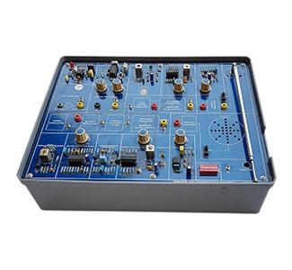
Analog Communication Trainer
Specification:
Analog Communication Trainer -
AMPLITUDE MODULATION AND DEMODULATION:NI-1001
Objectives: To construct amplitude modulator using transistor and observe the amplitude modulated waveforms and check the percentage of modulation.
To study A.M. demodulation by using diode demodulator
Specifications :
It has got three parts namely Carrier generator, AM modulator and AM demodulator.
Built in fixed power supplies of +12V, -12V @ 250mA.
Carrier generator using 8038 IC with fixed frequency 100 KHZ and fixed amplitude.
FREQUENCY MODULATION AND DEMODULATION:NI-1038
Objectives: To observe how the modulating signal changes frequency of the carrier rather than amplitude and observe the frequency modulated waveform.
To observe the changes in carrier centre frequency and to observe the frequency deviation.
To observe how the phase lock loop can be used for FM demodulation.
Specifications :
Built in fixed power supplies of +12V, -12V @ 250mA.
Carrier generator using 8038 IC with fixed frequency 50KHz and fixed amplitude.
And the direct method is used for modulation circuit with RC combination.
And also phase lock loop 565 IC and Op-Amp 741 IC is used in demodulator circuit.
BALANCED MODULATOR TRAINER:NI-071
Objectives: To observe that the output is a double side band, with a suppressed carrier signal.
To verify that the input audio level directly affects the double side band output amplitude.
To observe that the output is minimum with Zero audio input.
To measure carrier only output and the peak side band output, and to calculate the carrier suppression.
Specifications :
Built in a fixed power supplies of +12V, -12V @ 250mA.
1496 IC is used as balanced modulator.
Two potentiometers are provided to vary the carrier suppression.
CHARACTERISTICS OF MIXER TRAINER:NI-093
Objectives: To construct frequency mixer and to observe by giving two different input signals at base and emitter of the transistor and collector output is given to low pass filter to get the output frequency and observe the wave forms.
Specifications :
Built in fixed power supply of +12V @ 250mA.
2N 2369 NPN transistor is used as frequency mixer.
SYNCHRONOUS DETECTOR TRAINERS:NI-1051
Objectives: To construct synchronous detector circuit and to observe the detection signal of the AM modulator.
Specifications :
Built in fixed power supplies of +12V, -12V @ 500mA.
Built in variable carrier generator from 50KHz to 150KHz
Built in AM modulator circuit with external AF frequency and 1496 IC is used as synchronous detector.
SINGLE SIDE BAND SYSTEM TRAINER:NI-1065
Objectives: To construct a single side band system modulator and demodulator.
Specifications :
Built in fixed power supplies of +12V, -12V, +5V, -5V @ 500mA.
RF generator with fixed frequency 100KHz and variable amplitude 0-1.5VP-P.
AF generator with variable frequency 0-5KHz and variable amplitude 0-10VP-P. Automatic gain control (AGC) variation to adjust wave shape.
Two balanced modulators.
LSB, USB, demodulation blocks individually on one trainer.
Phase shifter method used for modulation.
RECEIVER MEASUREMENT TRAINER:NI-1067
Objectives: To observe the characteristics sensitivity, selectivity, fedility and Intermediate frequency response of AM receiver.
Specifications :
Built in fixed power supplies of +15V, -15V, +5V @ 500mA.
AF generator with variable frequency 200Hz to 10KHz and with variable amplitude.
RF generator with variable frequency 300KHz to 1200KHz and with variable amplitude.
Digital display for both RF & AF frequency read out.
IC 1619 is used for AM receiver measurements.
Built in AM Modulator.
PHASE LOCK LOOP TRAINER USING LM 565:Ni-1033
Objectives: To construct phase lock loop, frequency multiplier circuits and to observe lock and capture ranges.
Specifications :
Built in fixed power supplies of +5V, -5V @ 250mA.
565 IC, 741 IC and 7490 IC divided by 10 counter is given on board.
Different values of resistors and capacitors with one 10KΩ potentiometer is given to vary the output frequencies.
PHASE MODULATION TRAINER:NI–087
Objectives: To observe how a carrier's instant phase angle is made to vary in proportion to the modulating signals amplitude.
To observe the frequency deviation when the modulating signal crosses zero axis.
To observe how the phase change occurs when the modulating wave changes polarity. To observe how phase modulation is some times called as indirect FM.
Specifications :
Built in fixed power supplies of +15V, -15V @ 250mA.
IC 2205 is used as phase modulator.